

This page describes a DIY Voltage Controlled Oscillator project. I am very happy with this design, it is an iteration of the oscillator from my Turbo synth project, which had a design almost straight out of the LM13700 datasheet. This version makes some adaptions which on breadboard have proven to perform very well. This project should be easy to build on breadboard or veroboard, but does include some parts which are harder to source. Calibration is also a bit tricky and requires some tools you might not have – but is far from impossible.
A detailed description of the way this circuit works is included at the bottom of this page.
You can purchase a good quality PCB from me which has already been tried and tested through design revisions to work as described – coming soon
Hint: you can right click and select “View Image” to blow it up, but the link below might be better again:
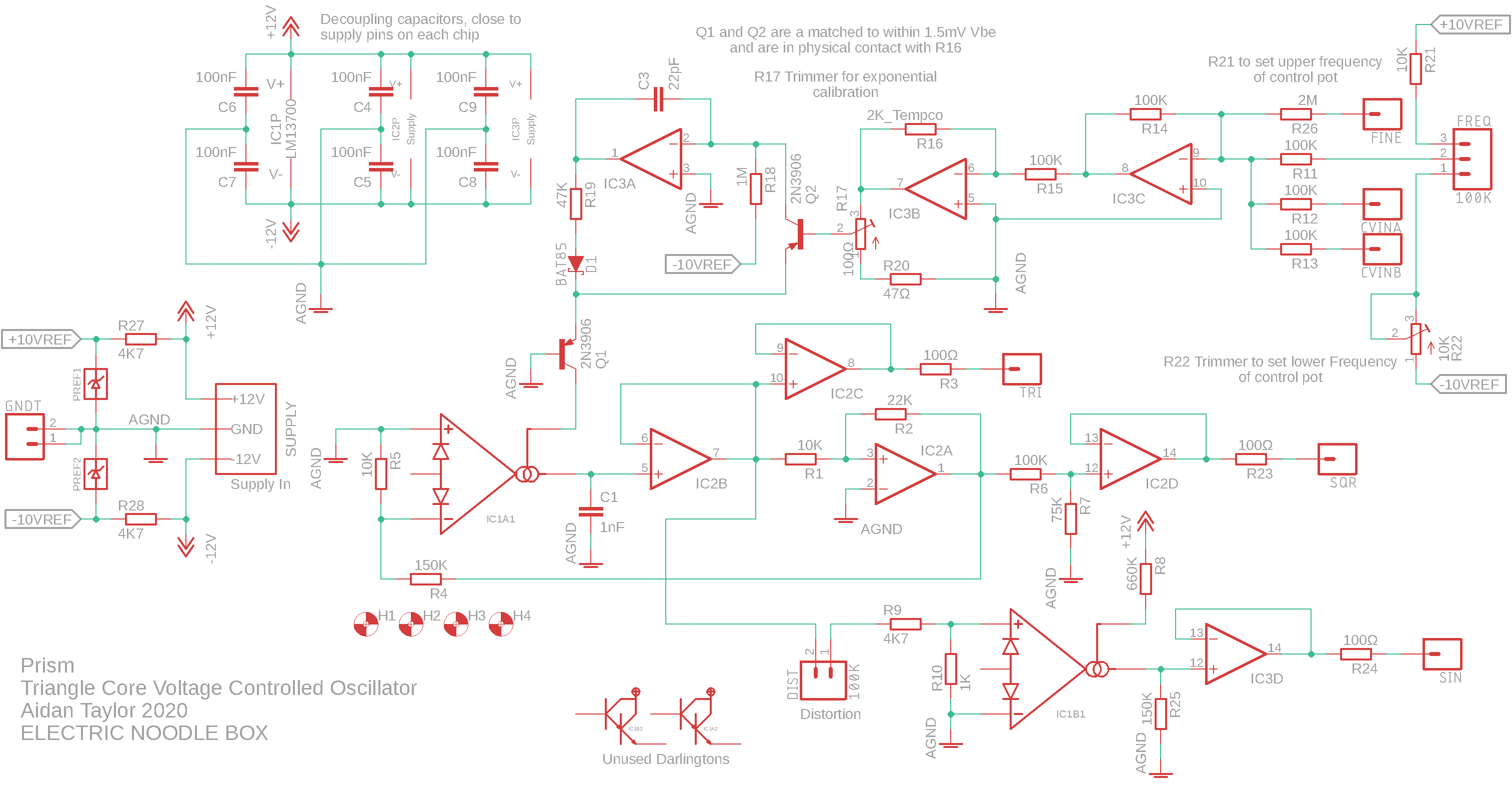
View the schematic in the repository
Specifics:
- Supply Voltage: ±12V Supply, there is localised ±10V precision reference
- Supply Current: ~18mA positive rail and ~18mA negative rail (maximum)
- CV Input: 0 – 10V (negative voltages will not hurt)
- Triangle, Square and Sine Signal Outputs: 10Vpk-pk (±5V)
Building
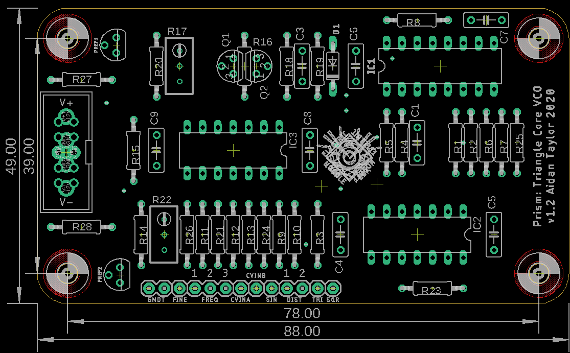
Resistor numbers are found on top of the part due to the small amount of available space, this means that it can be hard to locate a part if you have soldered up the PCB – use the image below to help locate parts. There are some things to pay special attention to in this build, detailed here:
Attention!
Prism’s Core PCB has some some special requirements. The 2n3906 pair should be matched, otherwise the VCO will not track properly. I offer hand matched pairs of transistors as an option when purchasing PCBs. Thonk also stocks them.
There is a 2K TempCo resistor which should be installed after the TO-92 transistors. The resistor lies across the top of the matched 2n3906 pair. Use bluetac or some other means to secure the TempCo as you solder.
Once the PCB or the module is complete, heatsink compound (Thermal Paste) should be added to thermally link the TempCo with the two transistors. Heat sink compound is evil stuff, it is normally toxic and will stain your clothes. It tends to get everywhere. I recommend that you apply a bit on something disposable, and use a small disposable implement, like a needle, to apply it. I have heard that it is also conductive, so you want to be careful not to cause a short circuit. See the pictures.


There is a .pdf with the layout to scale available here which also includes the routing, which might help if you are trying to locate an issue.
View the bill of materials here
This circuit can definitely be constructed on breadboard for testing, use a full size breadboard and spread out the three chips to allow yourself space to work. You will need a ±12V power supply at very least for testing.
I would recommend using a 10K potentiometer configured as an attenuator to ground for CVINB – which will allow control over FM depth. CVINA is for 1 volt per octave and wouldn’t normally be attenuated. See the image for control wiring (right click and select ‘view image’ to blow it up):
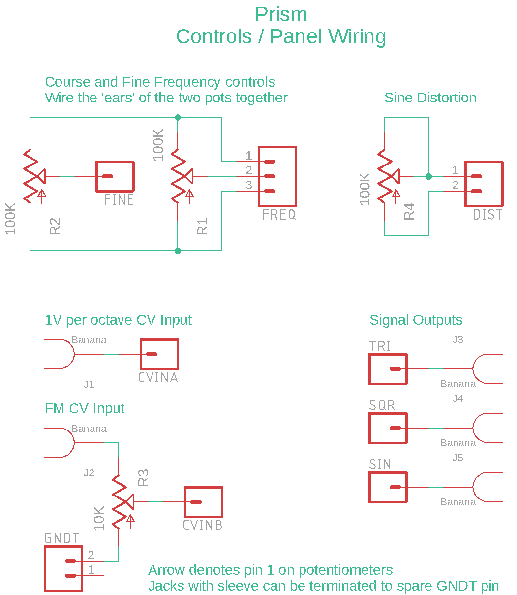
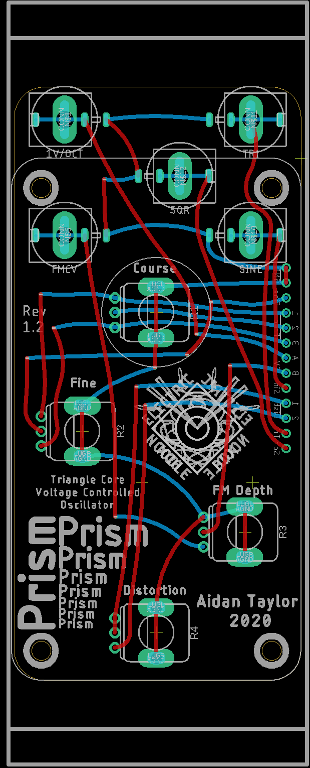
A control PCB and front panel is also available (coming soon) – this is Eurorack panel size standard, and can take either banana sockets or mini-jacks. Be aware that the banana sockets are specifically intended to be Cinch type, as these have a good vertical depth that matches the potentiometers used. The mini-jack footprint is for the PJ398SM (Thonkiconn) sold by Thonk. Link to BOM below.
Layout (to scale)
Calibration
I decided to rewrite this section having calibrated a few of these modules now. The TL:DR version is that you will need the module powered, you will need a way of measuring the output (the simplest is probably a guitar tuner or a tuning app on your phone), and a source of 1v/Oct like a keyboard or sequencer. Adjusting R17 sets the scaling of the 1v/Oct tracking. See the pictures below – it isn’t too hard to work out. For a more in depth explanation, read on:
Calibration can be achieved by adjusting trimmers R17 and R22. I can typically get five octaves of useable range. I use a guitar tuner with built in microphone, and then I check the VCOs track well together, which is important if you want to use FM or AM in musical ways. I have found that replacing R20 with a 75Ω makes calibration a little easier, as the adjustment will not be so course when turning the trimmer. It is important to note that this oscillator has a frequency range which can go from ~10Hz to ~21kHz, but it can only accurately track over ~5 octaves. The range that the oscillator tracks over will be determined by the centre frequency you calibrate it to, so it is best to pick a note that you want to track from (I usually use A2 or A3), and use that as your starting point.


Here is the procedure:
Set up the module so it is powered and there is no risk of short circuit by metal touching metal. Connect a 1V/octave source to the 1V/octave input. Connect the Square Wave output to an amplifier so you can measure with a tuner, or otherwise you could connect it to something with a frequency counter.
Turn the Course frequency pot fully anti-clockwise so the frequency is lowest, set the Fine frequency pot to centre position. If you are using a keyboard for your 1V/octave source, press the lowest C note or whatever key corresponds to 0V.
Now slowly turn up the frequency with the course pot and use the tuner to get a low ‘A’ note (you could aim for 110Hz or 220Hz which are the frequencies for A2 and A3), you can use the fine frequency pot to dial the note in precisely. I find that this note falls at around the ‘9 o’clock’ position on the course pot.
Now add 1V (or 1.2V) to the 1v/octave input by pressing the next octave key on the keyboard. The output should give you an impression of how much the scale needs adjusting: if the note is sharp then the scaling is too great, and if it is flat then the scaling is too small. Adjust the trimmer gradually, and observe the difference between the octaves so you can see how turning the trimmer affects the scaling.
As you adjust the scale, both octaves will shift out of pitch, you can use the Fine frequency control to correct as you go. Depending on where you have placed your center frequency – you will probably find that one of the octaves has shifted by more than the other, I find it less confusing to work by correcting the pitch at the octave that has shifted less, which is often the higher frequency octave. Adjust the scale so that you have the first octave within a few cents – you don’t need to be too precious here as calibrating the next octaves will increase precision here.
Once you have calibrated the first octave, move to the second and then to the third. You will find it easier as you go as most of the work was done in calibrating the first octave, further octaves will be more sensitive to change as you adjust the trimmer however. You should be able to get octaves two and three accurate, I normally find that octave four is hard to get perfect, but I can usually calibrate to within 2-4 cents.
Once you have completed this proceedure, your oscillator should track very well within this range, and will also track well for at least one octave below your starting point, and probably more.
To set the offset, I normally return the Course frequency to the lowest position (fully anti-clockwise) and set the Fine pot to centre. I then press octave four on my keyboard which should produce an audible frequency within my calibrated range. I then turn trimmer R22 to set the Offset to my key of choice (I use ‘A’).
Circuit Description
I recommend that you keep a copy of the schematic nearby to follow this description.
At it’s heart, this is a relaxation oscillator. Op-amp IC2A is configured as a comparator and will always output in a saturated state (a voltage close to either the positive or negative supply rail), the output of the comparator is connected to the inverting input of transconductance amplifier IC1G1 which has capacitor C1 to ground at its output. If the comparator starts in negative saturation, C1 will begin to charge resulting in a positive ramping voltage at this point in the circuit. Following op-amp buffers, this ramping output is connected back to the comparator, a set voltage threshold will eventually cause the comparator to ‘flip’ states so it becomes positively saturated, which in turn will cause C1 to discharge, resulting in a negative ramping voltage. The result of this combination is a consistent square wave oscillation at the comparator output, and a consistent triangle wave oscillation at the transconductance output. Resistor R2 sets hysterysis of the comparator, and this defines the peak to peak voltage of the triangle wave. As the comparator output is saturating close to the supply rails, a voltage divider is necessary to bring it to the desired audio signal level of 10Vpk-pk. The design uses a transconductance amplifier to control the rate that capacitor C1 charges and discharges, setting the transconductance gain consequently sets the frequency of the oscillation, much like a resistor would. The output of the transconductance amplifier is high impedance and considered more like a current than a voltage, which means it is essential to use a high impedence buffer to get a more useable signal. A TL084 has JFET inputs with suitably high impedence to do this well.
As this circuit only uses one half of the LM13700, the other is free to be used for something else. I found that a nice way to use this amplifier is to overdrive it with the triangle wave. The non-linear characteristic of the LM13700 results in something very close to a sine wave. This half of the circuit is an adaption from a design by Ray Wilson featured in his book “Make: Analog Synthesizers“. I found that Wilson’s circuit could be simplified and didn’t need as much biasing, resistor R8 reliably set the peak to peak amplitude of the output and the distortion can be adjusted via resistor R9, I decided to break this out in series with a panel potentiometer control which allows you to shape and distort the sine.
One thing I love about this design is the waveforms appear to be preserved perfectly across the entire frequency range. Without calibration on breadboard, the frequency could be set as low as 1Hz with the components specified, the triangle, square and sine wave were perfectly preserved in shape and amplitude, and the same could be said at the upper frequency of around 23kHz. I substituted capacitor C1 for a 1000nF ceramic capacitor which set the frequency range from 0.015Hz to 50Hz, perfect as an option to build this design as a voltage controlled LFO.
The last element to discuss is the voltage control, this section has some critical components, unfortunately some which are a little harder to find. I describe this design as critical because ultimately it will define the frequency of the oscillator. Human hearing has evolved to be incredibly sensitive to changes in pitch, much more sensitive than it is to changes in volume, so it is easy to hear things that are slightly out of tune. Noise or glitches in the control signal path will also be very noticeable. The voltage control takes steps to eliminate ‘noise’ in the control signal and translates a linear voltage to an exponential curve which is needed to achieve musical tracking at 1 volt per octave. Op-amp IC3C is an inverting summing amplifier. A potentiometer is used to set the main voltage bias which will translate as the main frequency setting of the oscillator, a second potentiometer can be connected to the ‘Fine’ control input, this has a large resistor in series which means it will only create a small bias, and a fine adjustment of pitch. A 2M resistor for R26 should result something near an octave in range, which I have found to work well. Both potentiometers are voltage dividers that use a 10V precision voltage referance, if they were connected directly to the power supply rails any noise or fluctuation present would be audibly translated into the pitch. The main frequency control has resistor R21 to set the upper frequency, and trimmer R22 to set the lower frequency, so you can calibrate the lowest frequency to be the pitch of a musical note if you choose. Without these resistors, I measured a frequency range of 10Hz to 23kHz (following calibration) on breadboard. Two other inputs are included which will allow for external voltage control to apply frequency modulation or note transposition. Following this summing stage is inverting amplifier stage IC3B, which has a gain of -0.02. 1 volt of DC change will result in -20mV change at the output. The feedback resistor R16 has a positive temperature coefficient (tempco) which is the first step in improving temperature stability, the purpose is significantly reduce ‘drift’ which describes a slow change in pitch over time (as the circuit or enclosure warms up, or the ambient temperature changes). R16 is in physical contact with Q1 and Q2 and thermal transfer paste should be carefully applied for good thermal conductivity. I use the 2K tempco resistors sold by Thonk in the UK which have a sensitivity of 3300ppm. Any resistor will change resistance proportionally to changes in ambient temperature, the tempco PPM rating describes approximately how much change will occur. Given that the circuit is expected to operate a little above room temperature, 3300ppm is derived as a close to ideal value for small changes around this point. Changes to R16 will ‘correct’ IC3B’s gain. Following this amplifier, trimmer R17 makes up part of a voltage divider so this output can be adjusted to something close to 18mV, which is fed into the base of Q2 – this trimmer critically allows you to dial in with reasonable accuracy the oscillators master frequency scaling in order to achieve 1V/oct.
Following the amplifier stages is the exponential converter. Let’s start by mentioning that this section works by exploiting a characteristic of BJT transistors, where the Base-Emitter junction voltage or Vbe has an exponential relationship to current flowing through the transistor. Doubling the current through the transistor will increase Vbe by about 18mV, or changing Vbe by 18mV will double the current through the transistor (apply rules of NPN or PNP types accordingly). To work backwards through this circuit block, Q1’s collector current is a current source for IC1G1’s amplifier bias pin which is biased to the negative supply rail -12V. Q1’s base is fixed at 0V by tying it to ground, and the emitter voltage is adjusted which will cause the collector current to double for every -18mVbe of change, adjusting the gain of the amplifier with an exponential operation. Vbe is highly subject to temperature fluctuations, and both active operation and ambient temperature will have an impact on the performance of Q1. So, Q2 and associated circuitry with IC3A result in a compensating current that adjusts with temperature. The base of Q2 is essentially the control voltage input for this section, the voltage at this point should be somewhere in the range of ±216mV. R18 is connected to the negative reference of -10V, which will set Q2’s collector to always be lower in voltage than the base and emitter, so current is always flowing. As R18 is also connected to the inverting input of the op-amp, the voltage at this point is more negative than the non-inverting input fixed to 0V, so the op-amp will attempt to balance it’s inputs by adjusting the current at it’s output. The output of the op-amp is connected through resistor R19 to the emitter of Q2, and will output as much current as necessary to effectively get a balanced current back across to Q2’s collector. As temperature change will effect Vbe of Q2, IC3A will compensate. Note that the emitters of Q2 and Q1 are tied together, so Q1 will follow Q2, and both transitors will be adjusted following any temperature change. In order for the converter to work effectively, it is essential that Q1 and Q2 are closely matched for Vbe, as the exponential voltage/current relationship will differ slightly for each individual transistor. Badly matched transistors make all of this effort pointless! It is also very important to note that this circuit expects Q1 and Q2 to ideally be at exactly the same temperature (which is near impossible, so we just have to do our best – a limitation of this design), if they are at different temperatures then they will of course respond differently to changes in Vbe.
As a final note, a discussion of this circuit block can be found in the “Nonlinear Circuits Handbook” which used to be very hard to find a copy of, but is now published in full online! See page 10 of this PDF on ‘Logarithmic Circuits’.

Hi Aidan,
thanks for doing the hard work and creating this site for your creations to be shared with everyone else.
I just had one quick question about the +10V and -10V reference voltage. Do you just use two Zener diodes (10V) in the places labelled PREF1 and PREF2? Or do you actually go ahead and use a Fixed Shunt Voltage Reference like the TI LM4040 or LM385?
Again, thanks for your hard work.
Cheers
John
LikeLike
Hi John, thanks for the question – sorry I missed it initially! I use an LM4040 for the oscillator precision references. Zener diodes will work as well, I try to keep the control voltage path as quiet as possible as any ripples or murmurs in the signal will absolutely translate into something you can hear! LM4040 are available from Farnell and Mouser in TO-92 package which fits the PCB
LikeLike
p.s. on the schematic, what are the items labelled H1, H2, H3 and H4? H is usually used for headers but not sure how that would work in this context.
Cheers
John
LikeLike
Hi John, this is lazyness on my part – H1 – H4 are just mounting holes, I create them in the schematic because I treat them like a part in the CAD software, so they are included in the PCB design (I could just draw the holes there, it would be no different!) – sorry for the confusion! 🙂
LikeLike