
This page describes an audio output module for an analogue electronic instrument that includes a simple AC mixer and an isolated output using an audio grade transformer. The design also includes a basic op-amp driven headphones amplifier. The op-amps used in this design are NE5532 by Texas Instruments, described as a superior op-amp for audio signal processing by Doug Self. I use an Oxford Electronical Products audio grade transformer which has a frequency response approximated to 60Hz – 25kHz. Controls allow for mixing of up to four signals and both the master output and headphones output can have seperate volume controls. This module will make a good output stage for a modular system, or an audio system with a number of signals – I have designed it with mono or split mono output in mind, it is not true stereo. This project should be easy to build on breadboard or veroboard, and the parts are easy to source.
A detailed description of the circuit can be found at the bottom of this page.
You can purchase a good quality PCB from me which has already been tried and tested through design revisions to work as described – coming soon
Hint: You can right click and “View Image” to blow the above schematic up, or alternatively use the link to view it as a .pdf in the browser:
View the schematic in the repository
Specifics:
- Supply Voltage: ±12V Supply
- Supply Current: TBA
- Signal Inputs: Up to four AC audio signals ±5V (DC will be cancelled)
- Signal Outputs: “Pro Line Level” split mono, and split mono headphones
Building
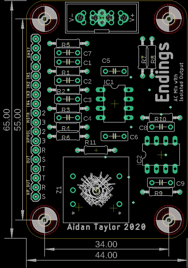
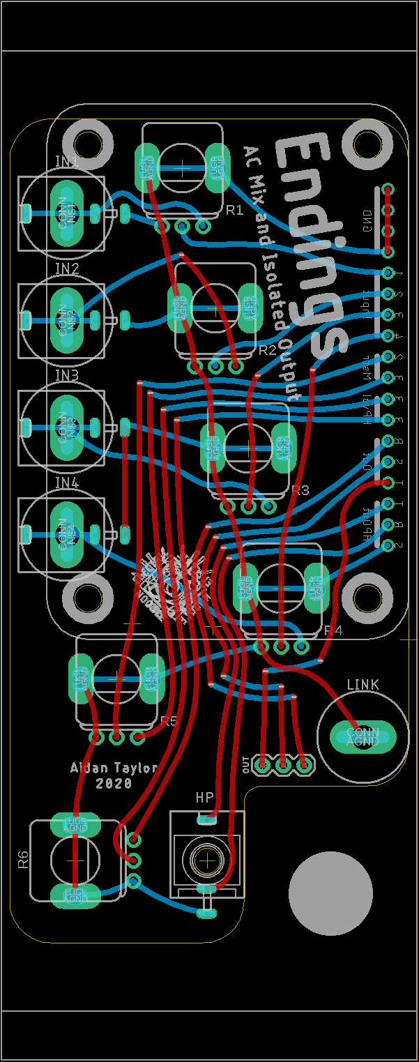
Resistor numbers are found on top of the part due to the small amount of available space, this means that it can be hard to locate a part if you have soldered up the PCB – use the image below to help locate parts.
There is a .pdf with layout to scale here
Find the bill of materials here
This circuit can definitely be constructed on a small breadboard for testing. You will need a ±12V power supply.
Each input should have a B10K or B100K pot for attenuation, by wiring pin 1 of the pot to ground, input to 3 and output from the wiper. Each output should use a logarithmic pot for smooth control, I use A100K potentiometers. See the wiring diagram below (right click and select ‘view image’ to blow it up):
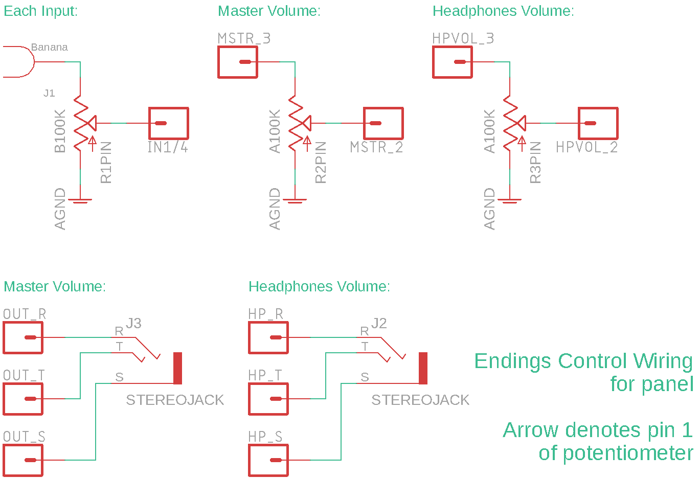
A control PCB is also available (coming soon) – this is Eurorack panel size standard, and can be constructed with either Cinch banana or mini-jack patch points. The master output is a 1/4″ TRS jack which needs to be wired, and the headphones output is a stereo mini-jack, please see the BOM (link below) for specific parts:
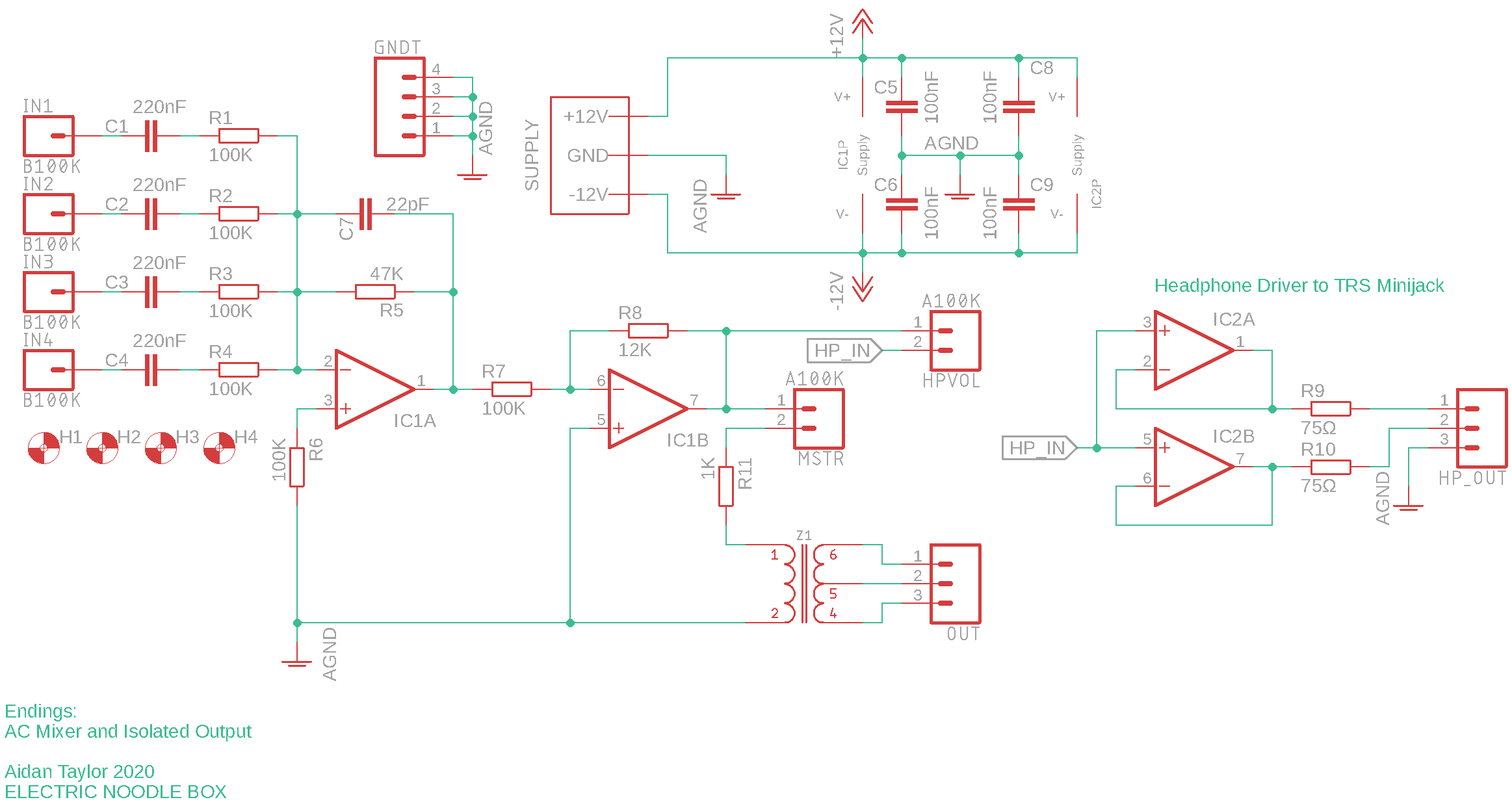
Circuit Description:
The design for this module is simple. IC1 is an NE5532 low-noise op-amp by Texas Instruments, which is a recommended Doug Self for building mixers and other audio electronics, Self is an expert in analogue audio signal processing and has published a number of books on the subject. IC1A is a summing inverting amplifier that accepts four inputs, each input has a series capacitor which will cancel DC offset present in the signal, making this an AC summing amplifier suitable for audio. Note that feedback resistor R5 will give this amplifier stage a gain of *-0.47, I didn’t want to reduce the signal too much in the case that only one signal was to be connected to the mixer, but this means it is quite possible to overdrive the amplifier when mixing multiple signals. IC1B follows the inverting AC summer and will invert the signal again and reduce the level significantly with a gain of *-0.12. The aim here is to output “Pro Line Level” signal at around ±1.44V maximum, as the previous stage IC1A will clip at ±12V.
The output is split at this stage, IC2 is a second NE5532 which is designed to drive headphones, IC2A and IC2B are both unity gain voltage followers that will provide a buffered output to drive each earpiece. The signal is also connected into the transformer. The Z1604 is an audio grade transformer with a tapped coil on one side. The datasheet states that the best frequency response is achieved when the transformer is driven at 0.2mW, so R11 is included to approximate this. I use the tapped side of the transformer for the output, you could either use a TRS style jack and use the two windings seperately for split mono to get an output close to half amplitude, or you can use both windings in series for a mono signal close to full amplitude. The transformer provides true isolation between the instrument electronics and the output. If you wish, you can totally skip the transformer and just wire across the coil terminals, this circuit will work the same but will no longer have the output isolation. If you do choose to skip the transformer, I would still keep R11 or a lower value resistor, that way IC2 is protected if the output is accidentally grounded.
