
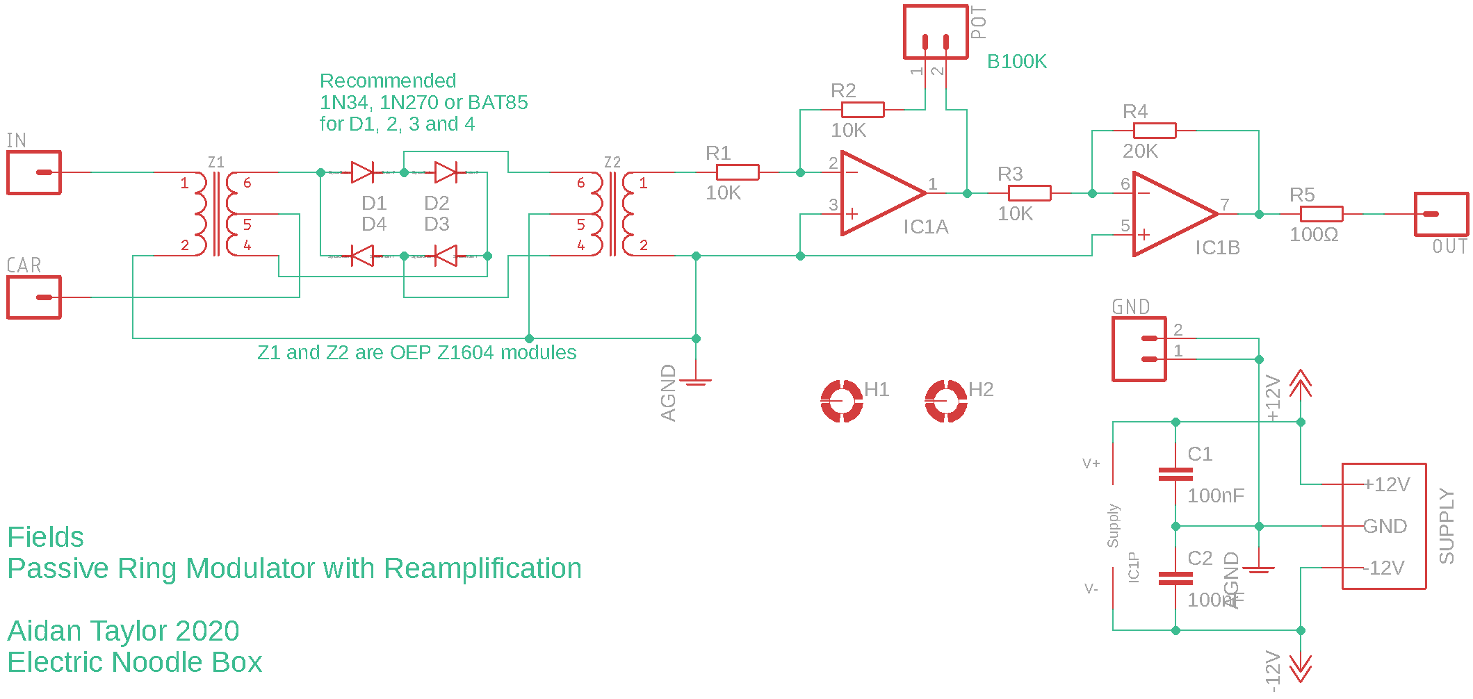
This page describes a DIY ring modulation module which can produce a wide variety of sounds, depending on the two input signals. It is an excellent companion to Prism. Ring modulation is a form of signal processing where the audio input (modulator) is affected by a second signal (carrier). The carrier is typically a sinewave, but other signals will work as well. The output is a product of the two input signals, when you listen you will hear two resulting sideband tones whose frequencies will be the sum and the difference of the inputs. The passive element of this module is made up by a pair of audio grade transformers, I use the Z1604 by Oxford Electronic Products which has a frequency range of approx. 30 – 25,000Hz. The ‘ring’ element is made up by germanium diodes, which have softer audible characteristics to silicon diodes, but you could use silicon diodes instead (the BAT85 might be a good choice as it is my first choice in a number of signal processing applications).
The module built to my specification has attenuators for both inputs, so the input level can be dialled in to get different sonic characteristics from the diodes. The output from the passive circuitry feeds in to an audio grade NE5532 op-amp with adjustable feedback, allowing you to boost the attenuated signal back to modular levels after attenuation.
This is a great DIY project for beginners!
A detailed description of the way this circuit works is included at the bottom of this page.
You can purchase a good quality PCB from me which has already been tried and tested through design revisions to work as described – coming soon
Hint: you can right click and select “View Image” to blow it up, but the link below might be better again:
View the schematic in the repository
Specifics:
- Supply voltage: ±12V
- Supply current: TBA (but very low, only the NE5532 needs power)
- Signal inputs (typically audio): 10Vpk-pk (±5V)
- Signal output: 10Vpk-pk (±5V)
Building
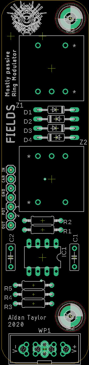
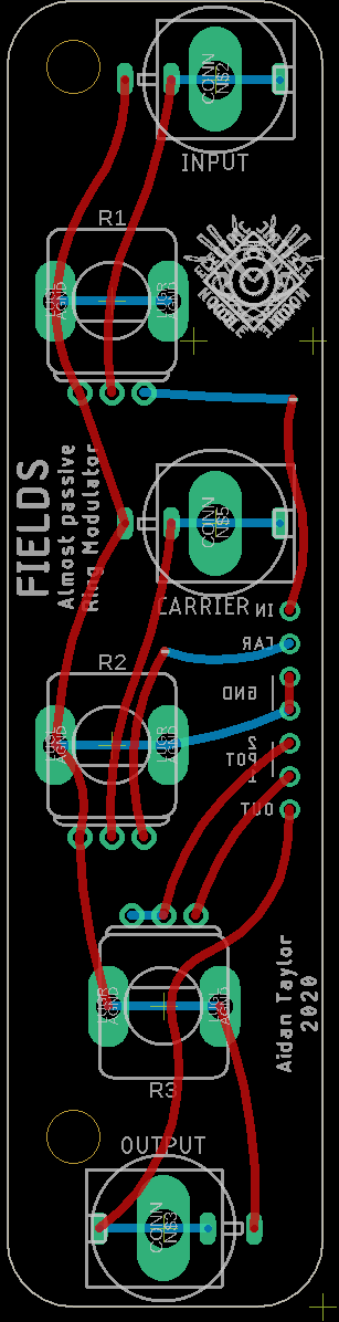
There is a .pdf file with the PCB layout to scale here which also shows the copper routing – this may help if you run into problems.
View the bill of materials here
This circuit can definitely be constructed on breadboard for testing, use a full size breadboard and spread out the components to allow yourself space to work. You will need a ±12V power supply for testing the active elements.
If you are wiring your own panel from the core PCB, I would recommend using 10K potentiometers configured as attenuators to ground for both inputs. See the image for panel wiring (right click and select ‘view image’ to blow it up):
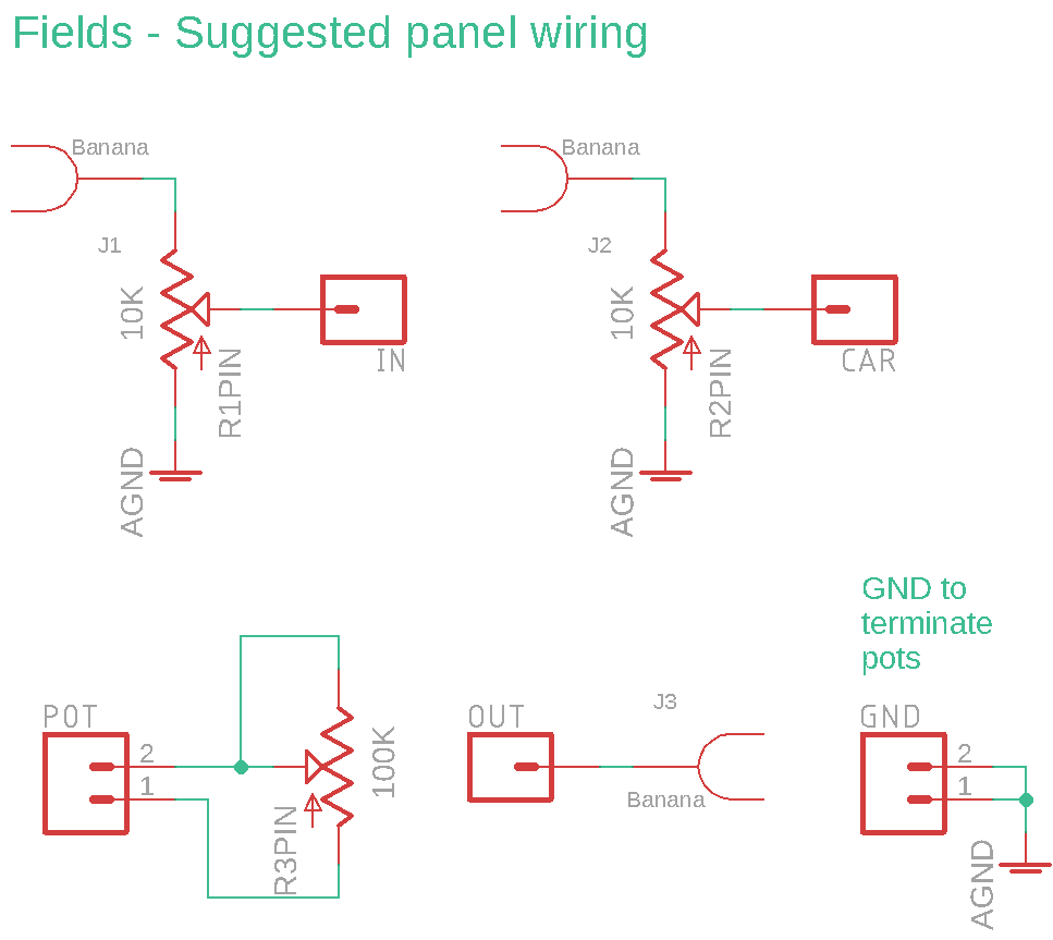
A control PCB and front panel is also available (coming soon) – this is Eurorack panel size standard, and can take either banana sockets or mini-jacks. Be aware that the banana sockets are specifically intended to be Cinch type, as these have a good vertical depth that matches the potentiometers used. The mini-jack footprint is for the PJ398SM (Thonkiconn) sold by Thonk. Link to BOM below.
