
This page details a DIY module project to build an audio echo or delay module which has a few voltage controlled settings. Like many before me, I designed this circuit with the PT2399 echo chip at the centre, which has been very popular for budget guitar pedals and the DIY scene for some time. I have made a number of devices using the PT2399, so this combines the knowledge from these previous iterations. The chip itself is digital and while offering a complete echo solution, it needs a variety of external components to work correctly. It has a small amount of memory and an internal oscillator sets the rate of a clock which iterates through a data stream, the data being made up by the continuous sampling of the audio input. The chip is designed for short delays, up to about 300ms, which is short but very similar to the capabilities of a bucket brigade delay. However, longer delay times can be achieved at the expense of sound quality. It isn’t a great quality sound at any rate – but the chip has a real charm to it which I have always liked, adjusting the delay time live will produce a gradual change in pitch which sounds a lot like a reel to reel magnetic tape device being adjusted and reducing the delay time extensively reduces the sound to digital sludge – great fun.
This module builds a couple of elements around the PT2399. Delay time is set with a voltage and has an exponential response so it feels responsive to adjustment and responds well to modulation. The input is preceeded by a VCA, so the echo is always on, but the input signal can be switched on and off and amplitude modulated. A second VCA is used to set a feedback path so the echo repeats. The input signal is mixed with the echo effect using a summing amplifier, with each broken out to an attenuator on the front panel so an external mixer isn’t necessary.
A detailed description of the way this circuit works is included at the bottom of this page.
You can purchase a good quality PCB from me which has already been tried and tested through design revisions to work as described – coming soon
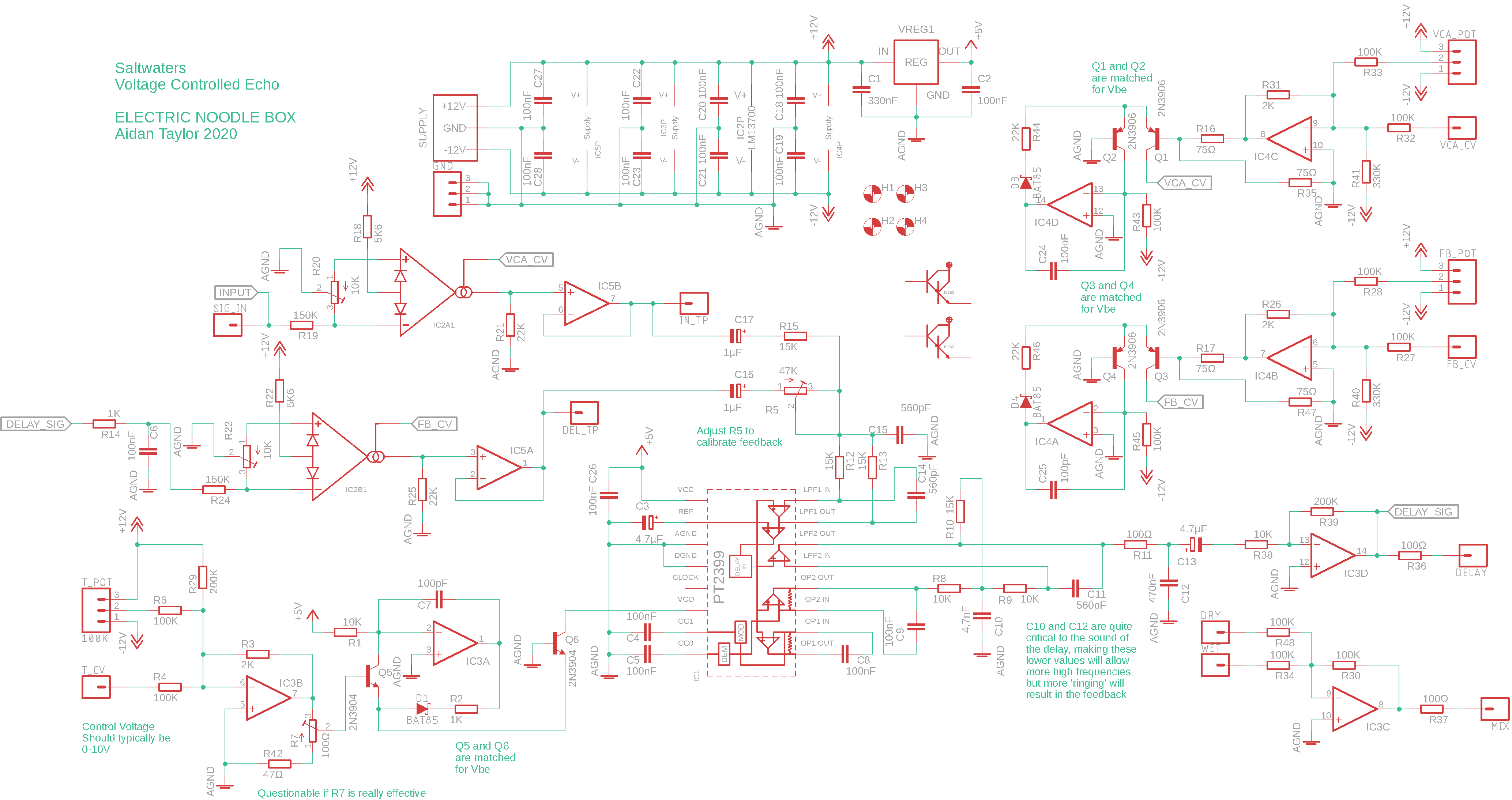
Hint: you can right click and select “View Image” to blow it up, but the link below might be better again:
View the schematic in the repository
Specifics:
- Supply Voltage: ±12V Supply
- Supply Current: TBA
- CV Input: 0 – 10V (negative voltages will not hurt)
- Signal Input and Echo Output: 10Vpk-pk (±5V)
Building:
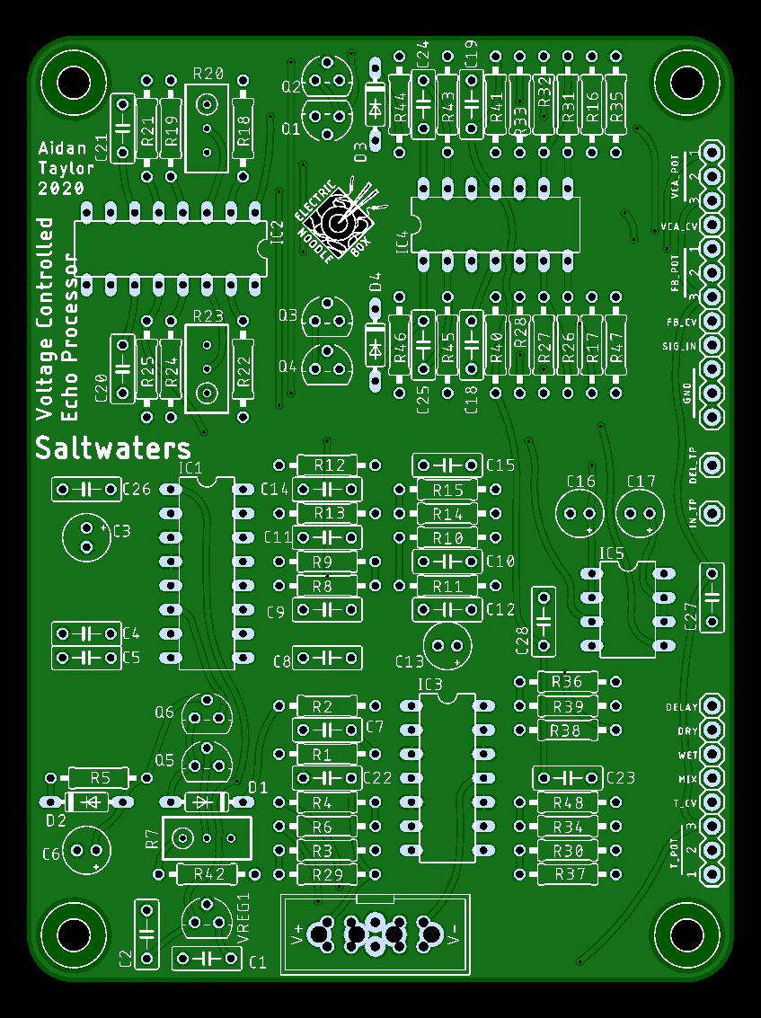
Resistor numbers are found on top of the part due to the small amount of available space, this means that it can be hard to locate a part if you have soldered up the PCB – use the image below to help locate parts.
The PT2399 is not stocked by typical electronics retailers that you can get most of your basic parts from. I use Tayda Electronics which is a Thailand based retailer and sells lots of parts which are good for audio DIY (particularly for guitar pedals). Rob Hordijk told me that he stopped making his ‘Zeitgeist’ delay because he found the PT2399 too variable – I haven’t had this problem myself, but you might want to purchase a couple if you want the security of having a selection, and you could solder a 16-pin DIP holder in place so it is easy to swap chips:
There is a .pdf with the layout to scale available here which also includes the routing, which might help if you are trying to locate an issue.
View the bill of materials here
This circuit can be constructed on breadboard for testing, use a full size breadboard and spread out the three chips to allow yourself space to work – I used two when working on this design so things weren’t too cramped. You will need a ±12V power supply for testing.
I would recommend using a 10K potentiometer configured as an attenuator to ground for CV inputs – I don’t include this for the input VCA on my control PCB but I do for delay time and feedback. See the image below for control wiring (right click and select ‘view image’ to blow it up):
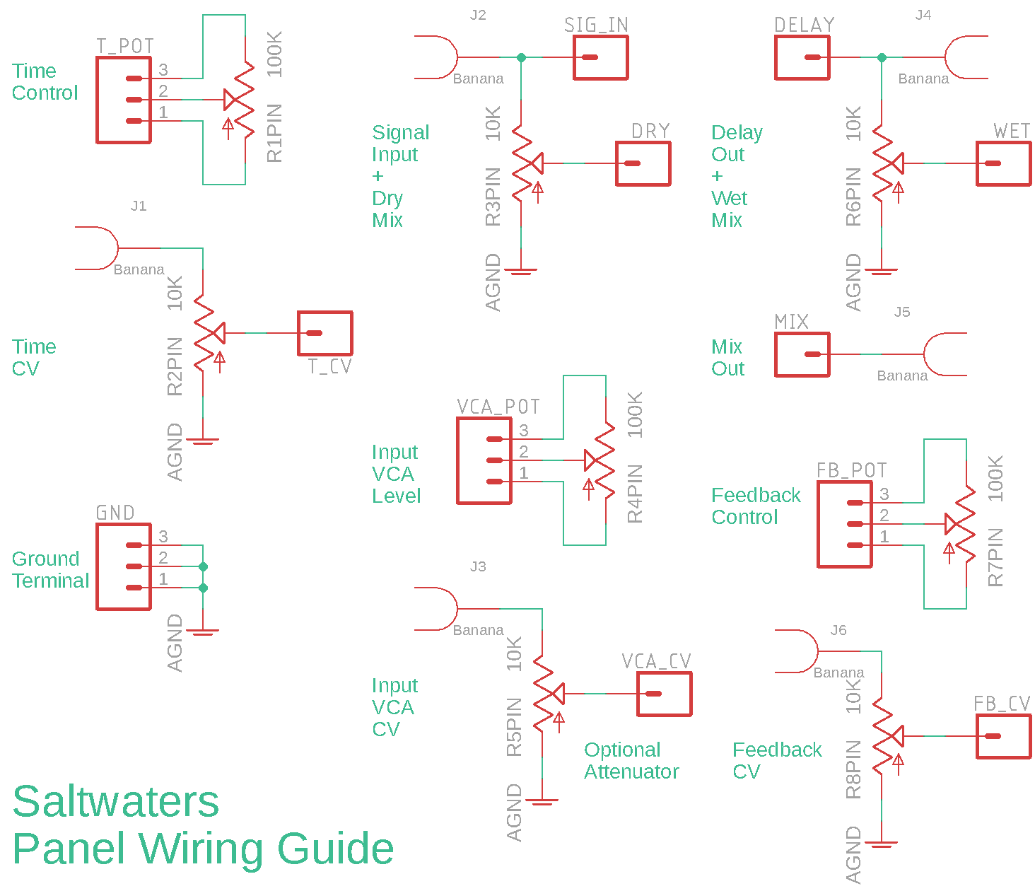
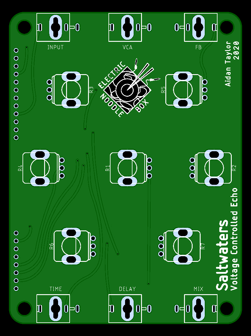
A control PCB and front panel is also available (coming soon) – this is Eurorack panel size standard, and can take either banana sockets or mini-jacks. Be aware that the banana sockets are specifically intended to be Cinch type, as these have a good vertical depth that matches the potentiometers used. The mini-jack footprint is for the PJ398SM (Thonkiconn) sold by Thonk. Link to BOM below.
