The Electric Noodle Box Modular Series is an expanding range of functional circuits that can be combined to build complete instruments or sound processing devices. The aim of this endeavour is to support you in making and learning about DIY sound projects. I also use these circuits in my own instrument design.
The Electric Noodle Box Modular Series circuits are open source hardware designs released under the CERN-OSH-W license. The aim is to help you learn how to build unique and exotic electronic instruments, and also to make building more accessible if you just wanna make. I chose to release designs this way in recognition of my own learning, made possible by the rich history of DIY sound electronics available in the public domain. Open source hardware allows for continued dialogue in making and inventing and I want you to be able to take part in the conversation, whatever point you are at in your own learning journey.
PCBs will be available for all designs, if you purchase a PCB from me then you are helping to support the existance of this site and my own learning which will contribute to improvements and options in the range. The PCBs offered are easy to build circuits using through-hole circuitry, and avoid rare, expensive and obsolete parts whenever possible. If parts are included in a design which are difficult to source, then they will most likely be made available to purchase along with the PCB. The designs do not (currently) include panel hardware layouts, as this allows the circuits to be integrated into the format of your choice.
At this point in time, I am evaluating a range of circuits so nothing is available other than design files just yet
Specification
In order for circuits to work together a design specification is helpful, it is recommended that you stick to this as a standard in order for each circuit to work as expected, particularly if you want to expand with your own DIY builds:
- Power Supply: Split/Bipolar ±12VDC, a footprint for a four way 3.96mm molex connector is available (MOTM style) combined with a 10 pin IDC header (Eurorack style) as the power supply input on each PCB. Some PCBs have local regulators for 5V.
- Precision Voltage Reference: Positive and negative 10V precision reference, is used locally on some boards
- Audio signals: 10Vpk-pk, or -5V to +5V
- Modulation signals: Output in the positive range 0V to 10V
- Gate and Trigger signals: 0V off, 10V on
- Attenuation: I recommend that attenuation with a B10K potentiometer configured as a voltage divider to ground is applied to any control voltage input, unless described otherwise in a design. Attenuation on outputs is less preferable as it reduces the patchability of a signal.
- Tracking: 1 volt per octave – other scaling (e.g. 1.2 volts per octave) is not difficult to achieve if desired
Colour Code:
I use Cinch banana jacks and Sifam/Selco knobs, these on my modules both look great and work well as a colour coded reference. I use the following colour code in my designs:
Bananas
- Blue: Audio signal output (also outputs that go below 0V)
- Orange: Audio input (or AC coupled input)
- Green: CV signal output
- Red: CV input (or DC coupled input)
- White: Clock / Gate / Trigger output
- Violet: Clock / Gate / Trigger input
Knob Caps
- Blue: Affects audio signal
- Orange: Audio / AC attenuator
- Green: Affects CV signal
- Red: CV / DC attenuator
- White: Affects clock / pulse / trigger
List of Modules
All design files are available in the repository, please be aware that I am currently constructing this, everything should be considered as a prototype and documentation is limited at this point in time.
- DC Module Split Power Supply – coming soon
- Battery Split Power Supply – coming soon
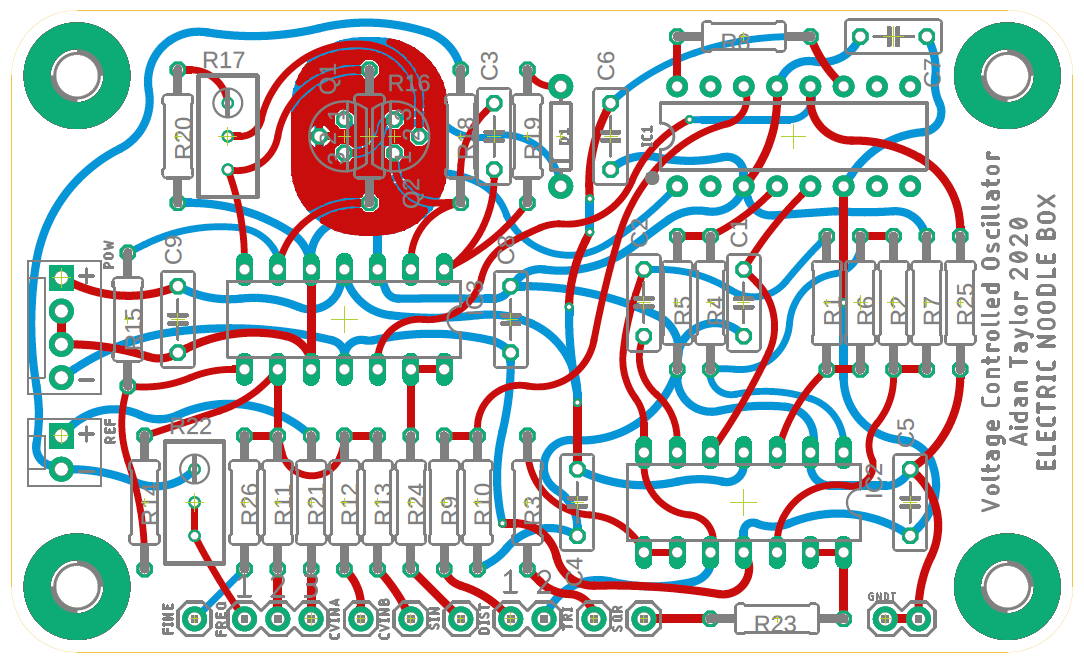
- Prism: Triangle Core Voltage Controlled Oscillator
- Portals: Dual Exponential Voltage Controlled Amplifier
- Transients: Dual Voltage Controlled Function Generator
- Knives: Dual Looping AR Function Generator
- Mirrors: Dual Attenuverter and DC Shift
- TimeSeed: Voltage Programmable Clock
- The Right Hand Path: Sequential Voltage Generator – coming soon
- The Left Hand Path: Fundamentals of Chaos
- Endings: AC Mixer with Transformer Isolated Output
- Ffrydiau: Complex Wave Distortion
