(Late Conclusions!)
If you are wondering, I haven’t been stuck at Tiree for a couple of weeks, I just didn’t get round to posting this final update! This blog post is long, and covers the multiple projects I was involved in at Tiree Tech Wave.
For the duration at Tiree I worked on four projects, as documented to some extent in my previous blog posts. These were:
- “Truth Serum”, an Arduino Due based MIDI sequencer
- “Touch Map”, (that’s my unofficial name for the project) a rear-projected, laser-cut map of the world made from wood, acrylic and brass pins. Touching the brass pins plays video and audio files. (Teensy and Max/MSP)
- “Physical Tweeting”, (again, my unofficial name) RFID tagged objects that send Tweets upon detection. (Raspberry Pi, Python and Node Red)
- Circuit Playground generative light experiments
Truth Serum
Truth Serum is an idea that I have bounced around in my head for some time – to make a sequencing tool for my Hordijk Modular and other MIDI capable instruments, but mainly for the Hordijk system as it doesn’t have dedicated sequencing built in and does have a MIDI input socket.
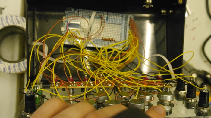
I worked on the enclosure to some extent before leaving for Tiree, but left all of the wiring and programming to do on site. I worked on the project solidly for the first two days of the Tech Wave and got basic MIDI note sequencing going in that time:
 The ongoing aim for the project is to have a flexible controller that is capable of traditional and non-traditional forms of sequencing. The project includes the following controls:
- 8 Potentiometers
- 2 Encoders (left)
- 2 “mode” buttons and 2 “function” buttons
- 8 toggle switches
The panel also includes 16 3mm yellow LEDs and 2 RGB LEDs.
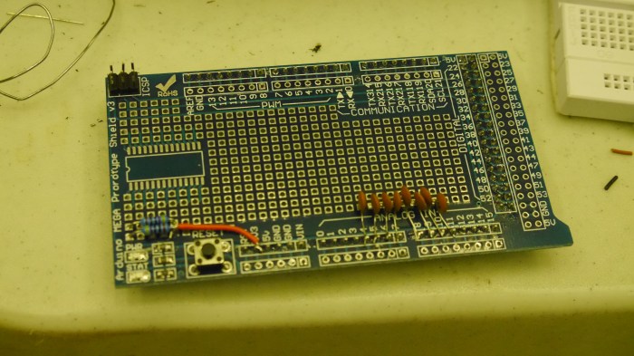
Before I left for Tiree I did some research into the feasibility of all the hardware and uncovered a couple of issues in my plan. The worst one was that I planned on controlling the LEDs in a matrix as I thought this would save on eating up digital pins – my basic plan was to have 8 anode pins and 2 cathode pins, you could think of these like X and Y controls for the matrix – the idea being to only have a single row active at a time. I planned on having two arrays (lists) which would have the LED states stored for each row (eg IOIIOOOI), and then by simultaneously rapidly cycling between the two arrays (writing to anodes) and activating the cathode pins you could create any configuration. In principle this idea is sound, but has a problem in that the amount of current you can sink to any digital pin of the Due is super low! See the specs here. Lighting multiple LEDs would require large resistors which would heavily reduce the brightness, or else risk permanently damaging the Due. I received some advice from Arduino.cc forumers on this and a couple of solutions were suggested – the most plausible suggestion I didn’t actually get explore for lack of time to order parts, and this was to use an LED matrix driver IC which could have been easily programmed from the Due and would have had effectively it’s own current supply (this is the route I will take for mark II!). What I ended up doing was to instead use a pair of NPN transistors to terminate the LED cathodes, so instead of sinking current to the pair of Due pins I used them to activate and deactivate the flow of current through a transistor:

I am very glad I looked into that before leaving for the Tech Wave! I decided to use 470Ω resistors as current limiters in the end as these still put out a fair amount of brightness and meant I was well within the safety limits for the Due, here are the LEDs under test at Tiree:
Once wired up, I tested all the hardware and found a few more problems – the buttons are spring latched as opposed to momentary. I can live with latching for now, but momentary would have been more flexible for programming (think tap-tempo and the likes). That’s something to fix for a later hardware revision now. The other problem is that the encoders are jumpy as heck and I haven’t figured out the magic ingredient to debounce them just yet. I tried using methods that work on an Arduino Due or even a ATMEGA32u4 based board, but these make the Due crash as they include delays (which in fairness shouldn’t actually work on the other boards either). I tried debouncing with soft switching and time based conditionals but didn’t get substantial results from this either. I opted for software debouncing instead of hardware (where you basically add some capacitors to the encoder pins) as I normally implement them this way. The encoders are an ongoing problem to explore and fix.
Hardware MIDI was something totally new for me and it took a little effort to get it working at all, this was mostly down to some bad solder joints. So it was satisfying to hear the sequencer spring to life! Truth Serum in its current state plays an 8 note sequence, a function button starts/stops the sequence and the potentiometers set the MIDI note for each step over a 5 octave range. The F1 encoder sets the sequence clock rate, but doesn’t work well or reliably at present.
You can download the code in its current state here if you want to take a look (I probably reverted the encoder programming to very basic functionality in that version). Variables are spread across the tabs which in hindsight is a really dumb way to work as I have to rearrange things everytime I make a change! I think for the sake of sanity they should all be on the top level tab even if this makes the code less readable.
One other issue that came up is the interface for the Reface DX synth I used for testing becomes very slow to respond when the sequence is playing – I’m not sure if that is my fault at the moment and will need to run some analysis to find out.
Touch Map
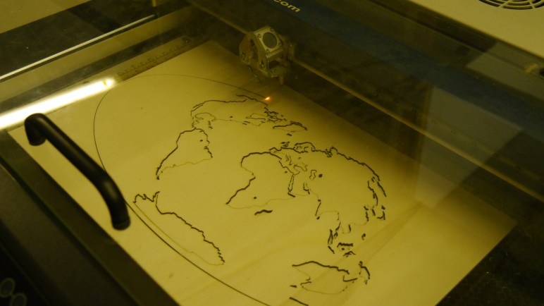
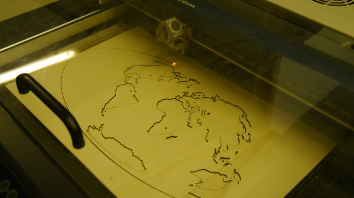
The touch map is a collaborative project carried out by FabCr8 members, the premise of this project is to develop some kind of interactive display that highlights Cardiff Metropolitan University’s international relationships. The grander idea is to have beautiful sculptural map of the world with perhaps touch sensitive copper trace lines running around countries or continents, and for it to run user uploaded video and soundbite content when interacted with. We rapidly developed a prototype that was a laser cut flat map of (most of) the world, made out of wood and acrylic that could be rear projected onto. We used a miniature laser projecter for the rear projection.
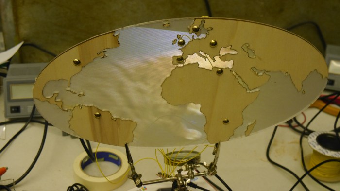
While being a little bit rough and ready, it looks surprisingly good in action, particularly in the dark. This was an idea generated by the group over the period we were at Tiree and constructed with the limited materials we had on site!
I contributed the electronics and multimedia development of this prototype which consisted of a Teensy setup and sketch based around capacitive touch and a reactive Max/MSP and Jitter patch. When the Teensy detected a touch on one of 8 points, it would send a MIDI message via USB. Max/MSP looked out for this message and would play one of 8 videos+sound in response. There are some nice tutorials on this blog already for working with Teensy and Max/MSP in conjunction.
Physical Tweeting
This was also a FabCr8 group effort with the same objective, though with perhaps a little less direction towards a solid outcome! 🙂 There was an interest in creating RFID tagged objects that could be exchanged or displayed in some way e.g. objects that were brought to the University from of for trips – the idea being that through RFID tagging the objects could have some media associated with them. It was widely agreed that RFID could be an interesting and flexible format to work with regardless. I hadn’t done anything like this before and got my teeth stuck in.
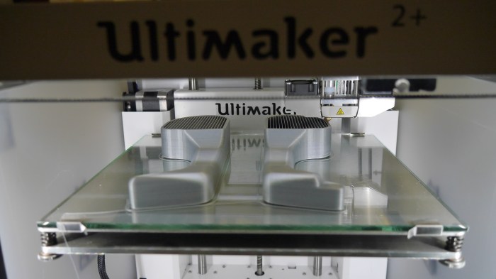
I had a basic idea that a device could be looking for UIDs – a unique identification number that each RFID tag holds – and upon detecting a recognised UID would send a Tweet. The idea was from there, a computer anywhere in the world could be looking out for particular tweets and could react to them in some way, such as by activating a piece of media. That was the rough idea. The multiple object idea was adapted by the group eventually into another world map, but this time on a 3D shape (I forget which type this is – geek level downgrade!) with RFID tags stuck on the faces, the idea being that if the shape was placed on a plinth with a particular face (a country/continent) highlighted to the viewer, then associated media content would be played on a linked device:


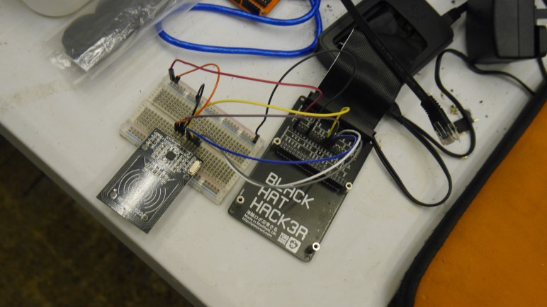
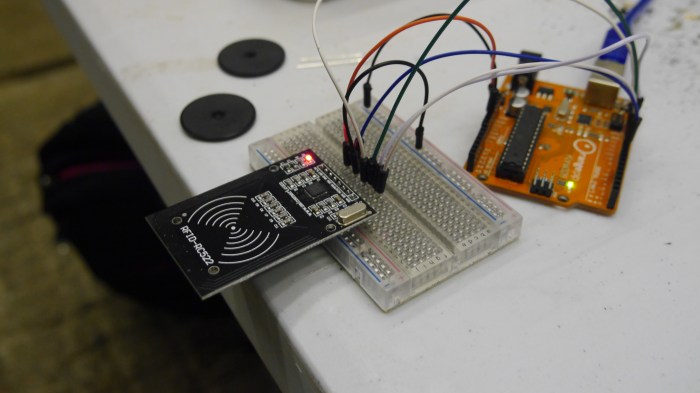
I first created an RFID detection sketch using Arduino, just to get an idea of how the data was handled (I’m more comfortable working with Arduino code). Once I had this working I then started porting the basic idea to a Raspberry Pi 3. The Pi 3 is a fully functional computer with a GPIO breakout, Bluetooth and WiFi connectivity and more. So it was a pretty ideal choice for prototyping around this idea. My skills in Python programming are really not up to scratch however, so getting this basic program to work ate up a good chunk of time at Tiree. I used a Python library for the RFID-RC522 reader which can be found here and made an adaption of the RFID-read example script for the project. The way I started out was to read RFID tags and print the detected UID to the Python virtual console, I scribbled these down and then adapted the script to look for the known UIDs, and to print a “Object x Found!” message in the case of detection.
That part wasn’t too bad, but where I struggled was actually trying to get that data out of Python in some useful form. I spent a fair amount of time barking up the wrong tree as I didn’t know the right question to google. I had already planned to work with Node-Red which is a web based visual programming app, very similar to Node-JS. Node-Red is designed for making web connected device to device communications very simple. That said, it is still pretty horrifying if you don’t know what you are doing! 🙂 Eventually I had help from another Tech Wave attendee, Tomas, who taught me about Web Sockets and helped me set one up in my Python script – I might struggle a little to set this up again, there were a couple of address settings that we whisked through without making a note of. Next time I will go through it a little more carefully and at least I have a tried and tested method.
So the final script detected individual UIDs and would then send a string via a web socket to a web tool built in Node-Red (which I don’t really understand at present so can’t explain too well). I used this web socket client library for Python which was pretty simple to set up. The Node-Red tool was also very simple, it just passed the unmodified string on as a tweet to a Twitter account I set up specifically for that purpose – you can have a look at the account here if you really want to, but there isn’t much of interest going on 😛
I found a small issue with the current setup in that Twitter would reject identical Tweets that were posted in a short time period. I tried to remedy this to some extent without success – I hoped to add a simple script in the pipe line on Node-Red that would take the string “Object x detected!” and make it “Object x detected for the nth time!”, so each tweet would be a little more unique – this was however beyond my skill level even though it may sound simple.
I felt like I achieved a lot with this project even though it didn’t get particularly far – I learned a lot of super useful stuff which I will surely be putting to use in other things in the near future! I really want to explore IoT connected devices more and it looks like web sockets and Node-Red will be instrumental in making interesting things happen. I will document my progress as I go and hopefully make it less painful for others in the future 🙂
Circuit Playground Experiments
Finally, in the spare snippits of time where I wasn’t making other things or drinking! …actually I did some of this stuff whilst drinking… I got to know the Adafruit Circuit Playground. The Circuit Playground as far as I can tell is an American answer to the BBC micro:bit with similar goals – to improve computer science skills in education. The hardware is currently under development but pretty much complete as far as I can tell, and Adafruit released a “Developer Edition” board to get some community input and testing. The board is pretty fun as it has 10 programmable RGB LEDs built in, an accelerometer, temperature sensor, light sensor, buttons, switches and a microphone and speaker! It is laid out as a wearable board so you can sow conductive thread to the pins just like a Lilypad. It is certainly a superb board for education and anyone wanting to cut their teeth with micro controller programming. I picked up a board from Cool Components in the UK who have a few in stock and it arrived just in time for Tiree.
I made a couple of fun sketches for the Circuit Playground which you are welcome to try if you have one. The first one is a touch sensitive generative light sensor:
I also made a sketch to play with the inbuilt buzzer – it can actually play musical pitches fairly accurately! This sketch plays a random sequence of notes from the major scale and adjusts the tempo depending on how much light the light sensor detects, because you know, computer science!
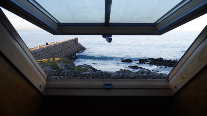
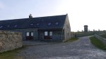
The Trip Home
What an amazing time spent with amazing people! Thank you to all involved should you see this message! And well done for reading this essay!

(photo from Charlie Bull)
So that is it – all that in 5 days was pretty full on. The journey home was about 16 hours long and made painful by huge stretches of motorway road works. We did stop at Loch Lomond on the way back which was stunningly beautiful on a misty day:
We also had an awkward sing along session that went on for about 8-hours – that must be some kind of record, though I doubt anyone was keeping tabs!
Until next time!